the first year of operation of the railway, a signal box was built at
Lakeside to control the signals and points in the vicinity of the station.
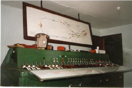
Track circuits are installed throughout the layout and the signal frame
is fully interlocked. The track arrangement has been changed several times
during the railway's life and the box now controls 15 signals and 8 sets
of points.
Signal Frame The signal frame is one of the few Westinghouse Type L still in operation
and the 35 lever frame was originally part of the Gloucester Road
(Croydon) box instalation. The levers are fully interlocked with the point
detection and track circuits. Unlike the original installation the interlock
logic is not performed by interconnecting the lever switches (D-bands)
and external relays, but a custom built micro-computer is used and the
logic performed by a program stored on an EPROM. The lever positions, point
detection and track circuits are used as inputs, and outputs from the computer
drive the interlock solenoids, point motor relays, signals and the track
diagram. With the exception of the signals, which use a low voltage AC
supply, all systems run from a constantly charged 12v car battery. Although
not really in keeping with railway tradition, doing it this way means that
the system can be easily updated to meet changing track layouts. The design
also has two totally automatic modes of operation built-in which enables
the railway to function in the absence of a signalman.
Signals The majority of signals are built using comercial vehicle marker lamp
housings running from a 12v AC supply. The approach signal to the station
complex is fitted with 12v 20w dichroic bulbs giving visibility of over
100 meters, even on sunny days. The signal at New Barn Halt (400m from
the box) is supplied with 110v from a standard industrial safety transformer.
All are operated by solid state switches in the box.
Points The points are operated by car windscreen motors modified to give 2
stop positions. They are contolled by relays driven by the box computer.
The car battery is used to absorb the high motor currents. The point position
is detected by microswitches directly operated by the blade tie bar.
Track circuits Unlike full size practice the track circuits are 'single ended' with
one rail permenently connected to ground. The other rail is fed with 12v
DC through a resistor and the voltage on that rail monitored electronically.
The monitor circuit is designed to deal with the intermittent rail-wheel
contact and the leakage caused by wet sleepers.
HOME